Battlebot(120lb) Brushed ESC
- smeltingpottutoria
- May 20, 2018
- 3 min read
The WPI robotics club competed at the 2018 robogames battlebot competition with a 120lb vertical spinner. This robot used two A28-150 motors for drive. These two motors are capable of providing a peak 6kW of power. At the time of creating this robot, there was a global shortage of the victor BB. This gave me a great opportunity to flex some of my new board design skills that I have been working on through various other projects.
With only a week to design the board before it needed to be ordered I spent time thinking about what configuration would give me the most efficient design. I decided that the separation of the logic board and the power electronics was crucial to making a reliable 5-10kW motor controller. Additionally, I was thinking about making this controller work for a different use case that I might explore down the road that required higher voltage support (72v+). Since I wanted separate boards, I designed the logic side to be able to support battery voltages from 15 to 100 volts. This meant that I could use the logic/driver board with different power boards depending on the use case.
Below is the logic board with all components populated about to be reflowed. Shown from top to bottom are the gate drivers, then the switching regulator for the 15v gate drive, and finally the 5v regulator for the micro and optocoupler input from an rc receiver. The logic board has an led to indicated when it has power and an additional two status leds for direction.

The power board that was designed for the 120lb robot drive ESC, it used eight 300A rated mosfets for the full bridge.


As shown above, the power board has an eight pin .1" header for the logic board to plug into. This also allows for easy replacement of the logic board since its the most likely part to fail. The main bulk capacitor is soldered on to the bottom of the board to keep the footprint of the esc smaller. The solder mask is kept off of the input traces to allow for copper bus bars or just extra solder to be added to handle more current. The gate drive resistors are hiding under the main cap on the bottom side of the board. This configuration uses 8AWG wire and has the leads going to the motor right in between of the fets to reduce the amount of heat created and to minimize the inductance while the bridge is switching heavy currents.
In addition to the ground plane on the bottom side of the logic board, a thin sheet of aluminum separates the power and logic boards when installed in its heat sink. This help reduce interference from switching. The logic board also has fast acting tvs diodes to catch any transients the may come from the power board during switching.
Below is the aluminum heat sink assembly that the power and logic board is encased in. The power board has compressed thermal pads and both the top of the fets and the bottom of the board to maximize thermal transfer. The case also physically constrains the capacitor and logic board in place so that nothing can be hit loose during combat


Above on the left is the new esc next to the previous heavy duty brushed esc.
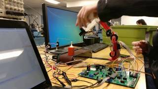
Below are videos of the esc being tested.