Battle Driver: The Third Generation
- smeltingpottutoria
- Jul 17, 2017
- 2 min read
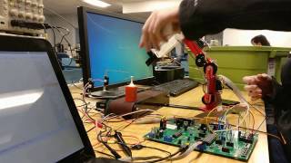
With the growing need to control larger and larger brushed dc motors for a variety of projects, I designed a bigger and better motor controller. With almost everything except the micro controller scrapped from previous generations, I decided to go with my favorite manufacturer of ICs, Texas Instruments. I decided to design this controller with the DRV8701 full bridge driver. This chip offers a wide voltage range of up to 45 volts, with the important feature of current control. This is probably the biggest upgrade from previous versions of the battle driver. The DRV8701 will chop the input drive signal in order to maintain a desired max current through the bridge. The last revision could monitor current and would be able to current limit, but wouldn't come close to reacting as fast as the DRV8701. Additionally, the board featured optocoupled pwm input, and a pot to adjust the current limit between 0 and around 160 amps.
The microcontroller used was the atmega328p but this time in a smaller 5mm x 5mm QFN package. With the new driver, there isn't any worry of self destruction from shoot through since the driver takes care of dead time. The bridge uses synchronous rectification to reduce the heat dissipation.
The bridge was designed with beefy FDBL9401_F085 fets with an on resistance of only 0.65 mili-ohms. The current shunt resistors are 1 mili-ohm a piece, bringing the bridge resistance to around 1.8 mili-ohms. The traces on the back of the board were left unmasked to allow additional solder to be added to decrease the total resistance.


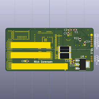


Above is the first version of the new motor controller. The board is much smaller compared to the previous design coming in at 2"x 1"x 0.25". A large (2200uF) bulk cap was soldered to the input pads to reduce the footprint of the board.


Above is the second revision of the DRV8701 based controller. A regulator was added to the bottom side of the board. This was due problems with the DRV8701 powering the micro. Additionally, a status led and calibration button were added to the top of the board. The calibration button was added to simplify the calibration process. Previously calibration was done by turning on the motor controller with a pwm signal above half throttle (1.5us). This proved to be more annoying than convenient.


(9/3/2017)
A case for the controller was constructed to increase the current capability of the controller and to increase robustness. The case is comprised of three layers of aluminum that are bolted together. Thermal pads were put on both sides of the board to increase heat dissipation from the copper on the board to the case.
Above are two videos testing the current capability of the controller with the new case.