Revision 2.0 DC Motor Controller
- smeltingpottutoria
- Mar 22, 2017
- 2 min read
This project is the second version of a custom brushed DC motor controller. This version had significant improvements in driving performance, max current, and additional features such as current sensing. This new version is designed for a new multi degree of freedom arm that I am working on. A new communication interface was added in addition to the existing PWM signal input. The idea behind this was that PWM is inconvenient and is a one way communication. Serial Peripheral Interface (SPI) was added so that information could be sent back to the master. This information, for example, could be current sensing information.
Another reason to use SPI is refresh rate. After testing I was able to achieve a stable update rate of 8kHz over spi. Meaning that the driver could be updated much more often than it could be over PWM, providing a much faster response time.
One downside to SPI is the minimum number of required connections for data transfer. PWM, assuming a common ground between master and slave, only needs one wire for data. SPI, assuming a common ground between master and slave, needs 4 wires (MISO,MOSI,CS,SCK).
But on the other hand, SPI doesn't require the use of a hardware timer like PWM does per each channel.
The motor controller micro used was the same as the previous, an Atmega328p. The main difference between the previous version of the motor controller was the use of P-Channel MOSFETs on the high sides of the bridge. This new revision used all the same CSD18563Q5A N-Channel MOSFETs. This required some way of driving the high side of the bridge with a voltage greater than the input voltage. The pre-driver used to accomplish this was the MC33883. This chip used a charge pump to drive the gates of the high side MOSFETs with a voltage at least 9 volts above the input voltage to the controller.
Below is picture of both the board as seem in eagle cad and the circuit diagram.


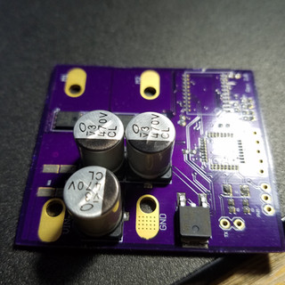
Below is a picture of the top and bottom sides of the 2 layer (1.90x2.14 inch) board from OSHpark.


Below are pictures of the assembly of the board. Solder paste was dispensed onto the board by my Voltera. After the components were placed on the board, the board was put onto the heated bed of the Voltera, and then the Voltera was used to reflow the board.